How To Make A Ball Joint: DIY Guide
Introduction
If you mean an automotive suspension ball joint, do not make a replacement part at home unless you have professional machining, heat-treatment, inspection, and testing equipment. A ball joint links the steering knuckle to a control arm. If it breaks, the wheel can move out of position or separate from the suspension.
For most cars and trucks in the United States, the safe choice is to buy a vehicle-specific replacement ball joint or replace the complete control arm. You can make a ball joint for a non-safety-critical project, such as a robot, trailer accessory, display model, or light-duty linkage. This guide explains both options and shows why a homemade suspension joint is risky.

What Is a Ball Joint?
A ball joint is a pivoting mechanical connection. It lets one part move through several angles while staying attached to another part.
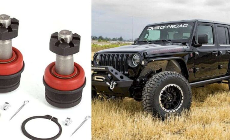
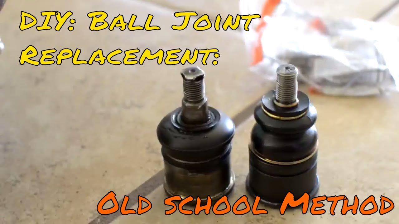
An automotive ball joint usually has these parts:
- Ball stud: A hardened metal pin with a spherical head.
- Socket or housing: The outer body that holds the ball.
- Bearing surface: A metal, plastic, or composite liner around the ball.
- Retainer: A cap, plate, crimp, or snap ring that keeps the ball inside.
- Dust boot: A flexible cover that keeps out water and grit.
- Grease: Lubricant that lowers wear and friction.
The ball stud often has a tapered end. That taper fits into the steering knuckle. The threaded end is secured with a nut and, on some designs, a cotter pin or locking nut.
A suspension ball joint must carry more than simple weight. It can face:
- Vertical vehicle load
- Braking force
- Cornering force
- Steering force
- Road shock
- Vibration
- Corrosion
- Repeated fatigue cycles
That combination makes an automotive ball joint a safety-critical component. A joint that feels solid on a workbench may still fail under road loads.
Can You Make an Automotive Ball Joint at Home?
You can physically machine the parts, but that does not mean you can make a safe roadworthy replacement.
A reliable suspension ball joint requires controlled material properties, accurate dimensions, correct surface hardness, proper preload, and proof testing. Most home workshops cannot verify all of these items.
The main risks include:
-
The ball stud may bend or break.
Ordinary mild steel is not a suitable substitute for a properly selected and heat-treated alloy steel. -
The socket may crack.
A cast or machined housing needs enough strength and fatigue resistance for repeated impact loads. -
The joint may have too much play.
Excess clearance allows wheel movement and causes unstable steering. -
The joint may bind.
Too much preload can restrict suspension travel or steering movement. -
The retainer may pull out.
The ball can separate from the housing if the cap, crimp, or snap ring is not designed for the load. -
The boot may fail early.
Dirt and water can destroy the bearing surface even when the metal parts look strong.
For these reasons, do not use a homemade ball joint on a passenger car, truck, ATV, or any vehicle that carries people on public roads. Use an engineered replacement with the correct dimensions and load rating.

How to Make a Ball Joint for a Non-Critical Project
For a small robot, test fixture, model, or light-duty linkage, you can make a simple captive ball joint. The design should still prevent the ball from escaping and should include a way to control play.
This method is suitable only when failure will not cause injury, loss of control, or major property damage.
Materials
You may need:
- A steel ball or spherical bearing ball
- A steel, aluminum, or strong polymer housing
- A matching socket or spherical liner
- A retaining cap or snap ring
- A threaded stud or bolt
- Low-friction grease
- A rubber or polyurethane dust cover
- Washers and locknuts
- A drill press or milling machine
- Calipers or a micrometer
- A deburring tool
- A torque wrench
A ready-made rod-end bearing, heim joint, or spherical plain bearing is often safer and easier than making the ball and socket yourself. It already has a controlled bearing surface and a known mounting method.
Step 1: Define the load and motion
First, decide how the joint will work.
Record:
- Maximum static load
- Likely shock load
- Required angle of movement
- Rotation speed, if any
- Exposure to water, dust, heat, or chemicals
- Expected service life
- Consequence of failure
For a simple linkage, the joint may only need to pivot a few degrees. A steering or suspension system needs much more careful analysis.
A useful first check is the estimated force:
[
F = m \times a
]
Where:
- (F) is force in newtons
- (m) is mass in kilograms
- (a) is acceleration in meters per second squared
This calculation is only a starting point. Shock loads can be much higher than static loads. If the joint supports a moving arm, include the arm's leverage and any impact force.
Step 2: Choose the ball and stud
Use a ball with a smooth, hard surface. A worn steel ball, random bolt head, or hardware-store sphere is not automatically suitable.
The stud must resist:
- Tension
- Shear
- Bending
- Thread damage
- Repeated fatigue
Avoid welding directly to the ball. Welding can change the metal's properties, create weak zones, and distort the spherical surface.
For a small prototype, a commercial spherical bearing with a threaded stud is usually the better choice. It gives you a known interface without requiring you to manufacture the most highly stressed part.
Step 3: Make the housing
The housing must fully support the ball while allowing the required movement.
A basic housing can include:
- A spherical cavity
- A side opening for the stud
- A retaining shoulder
- A threaded or bolted cap
- A grease port, if needed
- A drain or relief path for excess grease
The cavity should not have sharp edges. Sharp edges can damage the liner or concentrate stress.
Do not make the opening large enough for the ball to pass through. The retaining system must keep the ball captive even if the liner wears.
Step 4: Add a bearing liner
A bare steel ball inside a bare steel socket may gall, seize, and wear quickly. A liner gives smoother movement and helps distribute the load.
Common liner materials include:
- Acetal or similar engineering plastic
- Nylon designed for bearings
- PTFE-based composite material
- Bronze
- A purpose-made spherical bearing liner
The material must match the load, speed, temperature, lubricant, and environment. A plastic that works in a hand-operated model may soften under heat or creep under constant load.
Step 5: Install the retainer
The retainer is one of the most important parts of the joint. It must keep the ball in place without crushing the liner.
Possible designs include:
- Threaded cap
- Bolted cover plate
- Snap ring with a machined groove
- Pressed or crimped housing
- Two-piece clamped housing
For a prototype, a bolted cap makes inspection easier. Use locking nuts or thread-locking methods that suit the material and temperature.
Do not rely on glue, a thin washer, or friction alone to retain the ball.
Step 6: Set the preload
Preload is the light force that keeps the ball against the bearing surface. Too little preload creates play. Too much preload causes binding, heat, and rapid wear.
A practical adjustment method is:
- Clean the ball and socket.
- Apply a thin layer of suitable grease.
- Tighten the retaining cap gradually.
- Move the stud through its full range.
- Check for smooth motion.
- Check for side-to-side play.
- Lock the cap when the fit is correct.
The stud should move smoothly without rough spots. It should not flop freely under its own weight, but it should not require excessive force.
Do not guess at a torque value unless the design has a documented specification. Thread size alone does not determine the correct preload.
Step 7: Fit the dust boot
A dust boot protects the joint from grit, water, and chemicals. It must flex without pulling off at full movement.
Check the boot at:
- Full upward travel
- Full downward travel
- Maximum left and right angle
- Maximum rotation
- Any nearby moving parts
The boot must not rub on a sharp edge. A small tear can allow abrasive dirt into the bearing surface.
Step 8: Inspect and test the joint
Before using the joint, inspect:
- Retainer security
- Stud alignment
- Thread condition
- Smooth movement
- Excess play
- Cracks or burrs
- Boot sealing
- Grease coverage
- Clearance at every angle
For a load-bearing prototype, use a controlled test fixture. Apply the expected load slowly, then inspect the joint for permanent deformation, loosened hardware, cracks, and increased play.
A visual test is not proof of safety. If failure could hurt someone, use a certified component or have the design reviewed and tested by a qualified mechanical engineer.

How to Replace an Automotive Ball Joint Instead
Replacing a worn automotive ball joint is usually safer than trying to manufacture one. The correct procedure depends on the vehicle.
Some ball joints are:
- Pressed into the control arm
- Bolted to the control arm
- Riveted to the control arm
- Integrated into a complete control arm
- Built into a steering knuckle assembly
Use the vehicle manufacturer's service information for the exact procedure and torque values.
A general replacement sequence is:
- Park on a solid, level surface.
- Chock the wheels and loosen the wheel hardware.
- Raise the vehicle with a suitable jack.
- Support the vehicle on properly rated jack stands.
- Remove the wheel and inspect the suspension.
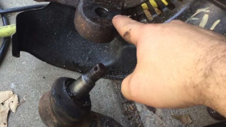
- Disconnect the ball joint from the steering knuckle.
- Remove the retaining hardware or press out the joint.
- Install the correct replacement part.
- Tighten fasteners to the vehicle's specified torque.
- Reinstall any cotter pins, locking nuts, or retainer clips.
- Reassemble the wheel.
- Lower the vehicle and torque the wheel hardware.
- Check alignment and road-test only when the repair is complete.
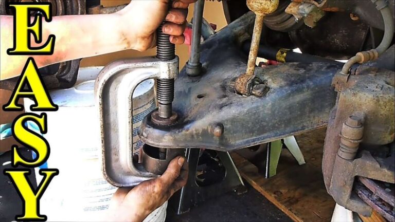
A press-fit ball joint often requires a ball-joint press. Do not strike a loaded suspension joint with a hammer while your hands or body are near the assembly.
After replacement, the vehicle may need a wheel alignment. Alignment is especially important if the ball joint affects camber, caster, or steering geometry.

How to Tell Whether a Ball Joint Is Worn
Common symptoms include:
- Clunking over bumps
- Uneven tire wear
- Wandering or loose steering
- Pulling during braking
- Vibration
- A change in camber
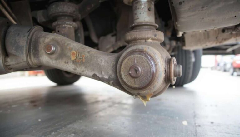
- Grease leaking from a torn boot
- Visible movement during inspection
These signs do not prove that the ball joint is the cause. Worn tie-rod ends, control-arm bushings, wheel bearings, struts, and tires can create similar symptoms.
Inspection methods vary by vehicle. Some joints are designed to show vertical movement as they wear. Others require a specific unloaded or loaded check. Follow the service manual instead of using one universal test.
If the joint has visible separation, severe looseness, a broken stud, or a damaged retaining feature, do not drive the vehicle. Have it repaired or towed.

Ball Joint Design Choices
The best design depends on the application. This table compares common options.
| Design | Best use | Main benefit | Main limitation |
|---|---|---|---|
| Commercial rod end | Prototypes and light linkages | Ready-made and adjustable | Often exposed to dirt |
| Spherical plain bearing | Controlled machinery | Smooth angular movement | Needs correct housing support |
| Polymer-lined socket | Low-speed projects | Quiet and simple | May creep or wear under load |
| Greasable metal joint | Serviceable equipment | Lubrication can extend life | Needs seals and maintenance |
| Automotive replacement joint | Road vehicles | Designed for a specific application | Must match the vehicle exactly |
| Homemade steel socket | Experimental projects only | Custom size and shape | Hard to verify for fatigue and failure |
For a public-road vehicle, the deciding factor is not whether the joint fits. It is whether the part has the correct strength, geometry, retention, and durability for that exact vehicle.

Common Mistakes to Avoid
Using a random steel ball
A steel ball may have the wrong hardness, surface finish, diameter, or load capacity. A small defect can become a fatigue crack.
Making the fit too loose
Loose clearance produces play. In a steering system, even a small amount of unwanted movement can affect control and tire wear.
Making the fit too tight
A tight joint can bind as temperatures change. It may also prevent the suspension from moving freely.
Welding the stud
Welding can reduce strength and create distortion. It can also damage heat-treated areas.
Leaving out the boot
A joint without a boot is exposed to grit and water. Grease alone will not protect it for long.
Using the wrong grease
Some plastics and elastomers swell or crack when exposed to certain oils and greases. Check material compatibility.
Reusing damaged locking hardware
A deformed cotter pin, stretched bolt, damaged thread, or one-time-use nut may not secure the assembly correctly.
Skipping alignment
A new joint can change suspension geometry. A vehicle that drives straight may still have incorrect alignment and rapid tire wear.

Frequently Asked Questions
Is it cheaper to make a ball joint than to buy one?
For a non-critical prototype, making a joint may reduce part cost if you already have the tools. For an automotive suspension, the machining, heat treatment, inspection, and testing needed can cost more than a proper replacement part.
Can I use a heim joint instead of a ball joint?
Sometimes, but not as a direct substitute. A heim joint may have different load capacity, misalignment range, weather protection, noise, and mounting dimensions. The complete design must support the loads and travel.
Can I rebuild a worn ball joint?
Some older or specialized joints are rebuildable. Many modern automotive ball joints are sealed and intended for replacement. Do not drill, refill, or modify a sealed joint unless the manufacturer provides a rebuild procedure.
What is the difference between a ball joint and a tie-rod end?
Both use a ball-and-socket connection, but they serve different suspension functions. A ball joint links suspension members while allowing steering and suspension movement. A tie-rod end transfers steering movement. They are not automatically interchangeable.
How much play is acceptable?
There is no single safe limit for every vehicle. Acceptable movement depends on the joint design and the manufacturer's inspection method. Use the service manual's limit. If you cannot find the correct specification, have the joint checked by a qualified technician.

Key Takeaways
- Do not fabricate a replacement automotive ball joint for a road vehicle in a home workshop.
- A safe joint needs suitable materials, accurate geometry, controlled preload, secure retention, sealing, and fatigue testing.
- For a robot or light-duty project, use a commercial spherical bearing when possible.
- If you build a prototype, test it only in an application where failure cannot injure anyone.
- Replace worn vehicle ball joints with vehicle-specific parts and follow the service manual.
- Get a professional inspection when the joint affects steering, suspension, or vehicle control.
Conclusion
The safest answer to “how to make a ball joint” depends on the application. A simple captive ball-and-socket joint can work for a low-risk project when it has proper retention, a suitable liner, controlled preload, and a protective boot.
An automotive suspension ball joint is different. It is a safety-critical part that must withstand repeated shock, steering, braking, and road loads. For a car or truck in the United States, use an engineered replacement part and follow the manufacturer's repair specifications rather than relying on a homemade design.